
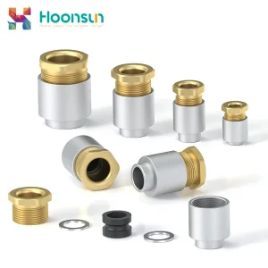
Industrial Grade Ingress Protection
High-Performance Cable Gland Product Portfolio (Tier-1 Series)
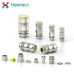
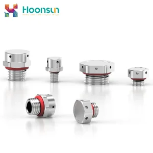
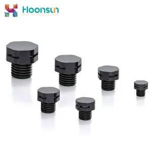
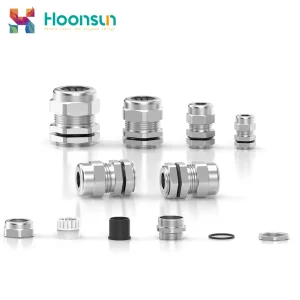
Engineered for mission-critical electrical enclosures, maritime vessels, hazardous chemical containment, and automation infrastructure. Every unit is 100% verified against rigorous thread tolerance and hydrostatic IP68 sealing standards.
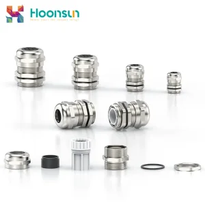
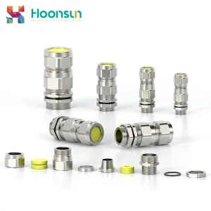
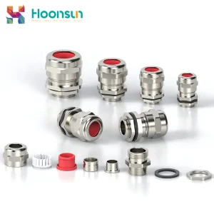
Supply Chain Excellence • Liushi Electrical Hub
Why Tier-1 EPCs and Global OEMs Source Cable Glands from China
Liushi in Yueqing, Zhejiang Province, functions as the undisputed epicenter of global low-voltage and industrial connection manufacturing. Over 70% of global industrial cable entries, conduits, and specialized gland hardware trace their metallurgical precision and tooling lineage to this interconnected manufacturing cluster.
20+
Years Continuous R&D
Dedicated tooling refinement and metallurgical formulation since 2006.
100%
Batch Lot Traceability
Spectral metal analysis and optical coordinate measuring machine (CMM) verification.
50M+
Annual Component Yield
Automated CNC multi-axis turning and high-speed robotic seal assembly.
10 Bar
Hydrostatic Test Rating
Continuous immersion rating exceeding standard EN 60529 requirements.
Full Vertical Integration
Unlike regional distributors or trading intermediaries, our Yueqing factory controls the entire manufacturing pyramid: direct copper-zinc raw alloy ingot casting, in-house bar extrusion, computer numerical control (CNC) Swiss precision threading, proprietary nitrile/silicone polymer vulcanization, and robotic packaging.
- Zero sub-contractor markups on custom tooling
- Strict DIN CW614N & CW617N metallurgical consistency
- Guaranteed ±0.02mm pitch tolerance on automated threads
Global Certification Harmonization
Engineering teams exporting machinery globally face fragmented regulatory regimes. Chinese manufacturing centers bridge this via quad-standard qualification across Metric, PG, NPT, and G systems, backed by recognized third-party test verification.
- UL 514B Listed & CSA C22.2 No. 18.3 compliance
- ATEX / IECEx Zone 1 & Zone 2 hazardous certifications
- RoHS 3 (EU 2015/863) & REACH SVHC lead-content thresholds
Rapid OEM Customization & Tooling
Custom enclosure wall thickness, non-standard armored braiding, high-vibration automotive harnesses, and marine salt-fog environments require rapid iteration. Our tool-and-die team transforms CAD models to production samples in under 7 business days.
- Extended entry thread lengths (15mm to 35mm custom)
- Fluorosilicone (FVMQ) / EPDM / Viton seal customization
- Custom laser marking & private OEM distribution packing
Master Technical Sizing Reference
Authoritative Electrical Cable Gland Sizing Matrix (Metric • PG • NPT • G)
Proper cable gland specification hinges on three geometric parameters: major thread outside diameter, clearance drill hole diameter, and the elastomeric compression sleeve's clamping range. Use this engineering matrix for precise CAD layout and mechanical enclosure punch-out planning.
EN 62444 ISO Metric Coarse Cable Gland Sizing Standard (M12 – M63)
| Thread Spec (Metric) | Nominal Major OD (mm) | Thread Pitch (mm) | Panel Clearance Hole (mm) | Cable Clamping Range (mm) | Wrench Hex Size (Nut/Body mm) | Min Thread Length (mm) | Recommended Torque (N·m) |
|---|---|---|---|---|---|---|---|
| M12 × 1.5 | 12.00 | 1.5 | 12.3 ± 0.2 | 3.0 – 6.5 | 16 / 16 | 6.5 | 3.5 – 4.0 |
| M16 × 1.5 | 16.00 | 1.5 | 16.3 ± 0.2 | 4.0 – 8.0 | 20 / 20 | 7.0 | 4.5 – 5.0 |
| M20 × 1.5 (Standard) | 20.00 | 1.5 | 20.4 ± 0.2 | 6.0 – 12.0 | 24 / 24 | 8.0 | 7.5 – 8.5 |
| M25 × 1.5 | 25.00 | 1.5 | 25.4 ± 0.2 | 13.0 – 18.0 | 30 / 30 | 8.0 | 10.0 – 12.0 |
| M32 × 1.5 | 32.00 | 1.5 | 32.5 ± 0.3 | 18.0 – 25.0 | 36 / 36 | 9.0 | 14.0 – 16.0 |
| M40 × 1.5 | 40.00 | 1.5 | 40.5 ± 0.3 | 22.0 – 32.0 | 46 / 46 | 10.0 | 20.0 – 22.0 |
| M50 × 1.5 | 50.00 | 1.5 | 50.6 ± 0.4 | 32.0 – 38.0 | 55 / 55 | 11.0 | 28.0 – 32.0 |
| M63 × 1.5 | 63.00 | 1.5 | 63.8 ± 0.4 | 37.0 – 44.0 | 68 / 68 | 12.0 | 35.0 – 40.0 |
DIN 40430 / ANSI B1.20.1 German PG & American NPT Taper Sizing Standards
| Thread Spec | Major OD (mm / inch) | Pitch / TPI | Clearance Hole (mm) | Cable Clamping Range (mm) | Standard Enclosure Type | Sealing Compound |
|---|---|---|---|---|---|---|
| PG 7 | 12.50 mm (0.492") | 1.270 mm (20 TPI) | 12.8 ± 0.2 | 3.0 – 6.5 | Small Sensors / Instrumentation | NBR / Neoprene |
| PG 9 | 15.20 mm (0.598") | 1.411 mm (18 TPI) | 15.5 ± 0.2 | 4.0 – 8.0 | Industrial Solenoids & Valves | High-Elastic NBR |
| PG 11 | 18.60 mm (0.732") | 1.411 mm (18 TPI) | 18.9 ± 0.2 | 5.0 – 10.0 | Machinery Pushbuttons & Relays | NBR / EPDM Option |
| PG 13.5 | 20.40 mm (0.803") | 1.411 mm (18 TPI) | 20.8 ± 0.2 | 6.0 – 12.0 | European Standard Power Entries | NBR / Flame Retardant |
| PG 16 | 22.50 mm (0.886") | 1.411 mm (18 TPI) | 22.8 ± 0.2 | 10.0 – 14.0 | Heavy Motors / Terminal Boxes | Modified Polyamide / NBR |
| PG 21 | 28.30 mm (1.114") | 1.588 mm (16 TPI) | 28.7 ± 0.3 | 13.0 – 18.0 | Distribution Feeders & Transformers | Oil-Resistant Elastomer |
| NPT 3/8" | 17.14 mm (0.675") | 18 TPI (Tapered) | 17.5 ± 0.2 | 4.0 – 8.0 | North American Industrial Automation | Neoprene / PTFE Flange Seal |
| NPT 1/2" | 21.34 mm (0.840") | 14 TPI (Tapered) | 21.8 ± 0.2 | 6.0 – 12.0 | UL 508A Control Panels & J-Boxes | Buna-N / Viton Extreme |
| NPT 3/4" | 26.67 mm (1.050") | 14 TPI (Tapered) | 27.2 ± 0.3 | 13.0 – 18.0 | Commercial HVAC & Rig Ingress | Heavy NBR Seal / O-Ring |
| NPT 1" | 33.40 mm (1.315") | 11.5 TPI (Tapered) | 34.0 ± 0.3 | 18.0 – 25.0 | Hazardous Conduit / Marine Feeds | Flame Proof Silicone / NBR |
Mechanical Standards Comparison
Thread Systems Demystified: Metric vs. PG vs. NPT vs. G (BSPP)
Cross-border engineering procurement frequently fails at the interface between regional thread standards. Understanding thread flank geometry, taper angles, and seal seating mechanisms is vital to preventing site catastrophic fluid penetration.
Metric (ISO 68-1 / EN 62444)
Characterized by a symmetrical 60° thread flank angle and standard 1.5mm pitch across most industrial sizes. Relies exclusively on a parallel mechanical thread engagement, requiring a captive O-ring or flat sealing washer against the enclosure face to achieve IP68 hermetic sealing.
Flank: 60°
Form: Parallel
Global Benchmark
PG (Panzergewinde DIN 40430)
Historical German steel conduit standard featuring an 80° thread flank and shallower depth. While superseded in general European EU building installations by EN 50262/EN 62444, PG remains heavily specified in global machine tooling, robotics, and German-designed factory automation retrofits.
Flank: 80°
Form: Parallel Short
Robotics / Legacy
NPT (ANSI / ASME B1.20.1)
The standard for North American industrial facilities and oil & gas rigs. Features a 60° flank with a 1° 47' taper (3/4" taper per foot). The seal is achieved across the spiral thread root-to-crest interference fit itself, frequently supplemented with PTFE thread sealant for gas-tight explosion isolation.
Flank: 60°
Form: 1:16 Tapered
USA / CSA Standard
G / BSPP (ISO 228-1)
British Standard Pipe Parallel threads featuring a 55° Whitworth rounded crest and root profile. Commonly deployed in marine shipbuilding, fluid power manifolds, and hydraulic power skid assemblies throughout the UK, Commonwealth nations, and maritime shipping fleets.
Flank: 55°
Form: Parallel Whitworth
Marine & Fluid Skids
Engineered Systems & Field Realities
Mission-Critical Cable Management Applications
Cable entry components represent the smallest percentage of capital expenditure on an industrial project, yet account for over 38% of field electrical breakdown callbacks when incorrectly matched to atmospheric conditions.
Electric Mobility & Energy Storage (ESS)
High-voltage battery junction enclosures and MW-scale utility power conversion systems require dual-sided shielding. Our cable glands prevent high-frequency inverter ripple noise with internal 360° brass conical grounding rings while guaranteeing IP69K hot-wash ingress resistance.
- Continuous 800V DC harness strain mitigation
- Liquid cooling quick-disconnect integration options
Offshore Wind Turbines & Marine Vessels
Maritime installations experience aggressive sodium chloride crystallization and thermal siphon pressure shifts. TH standard marine brass and SS316L cable glands prevent inner jacket capillary water draw via dual-seal chamber compression and integrated pressure equalization breathers.
- 1,000-hour ASTM B117 neutral salt spray endurance
- DNV-GL compliant steel wire armor (SWA) clamping
Hazardous Refineries & Chemical Processing
Flameproof (Ex d) and Increased Safety (Ex e) environments demand barrier gland designs where individual conductor interstices are hermetic against volatile gases. Our explosion-proof cable glands provide cold-flow mitigation and certified containment against internal ignition transfer.
- Certified ATEX II 2G Ex d IIC Gb / II 2D Ex tb IIIC Db
- Operating temperature span: -60°C to +140°C (Silicone)
Quality Assurance & Vendor Qualification
Global EPC Procurement Checklist for Chinese Cable Gland Suppliers
Purchasing departments must look beyond catalog pricing to verify factory metallurgical pedigree, test rig compliance, and automated quality controls before issuing high-volume purchase orders.
1. Material Spectroscopy
Insist on mill test reports (MTR) verifying copper purity (≥58% in CW617N brass) and low lead concentrations (<0.1% for RoHS/REACH compliance). Substandard suppliers frequently substitute recycled scrap brass that cracks under mechanical torque.
2. Torque-to-Failure Ratio
Evaluate proof torque curves. High-integrity Chinese factories mandate cap nuts survive 150% of nominal installation torque without thread shear, flange distortion, or premature seal blowout.
3. Hydrostatic & Dust Ingress Rig
Demand unedited third-party test videos of IPX8 immersion tanks (simulating 5 to 10 bar continuous pressure) and IP6X talcum powder negative-pressure chambers operating continuously for 8 hours.
4. Cable Pull-Out Resistance
Ensure compliance with EN 62444 Type A or Type B cable retention. The gland clamping assembly must resist axial pull forces up to 450N without allowing cable slippage or outer sheath displacement.
Specialized Hardware Program
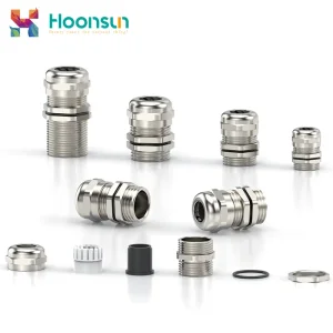
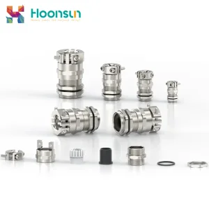
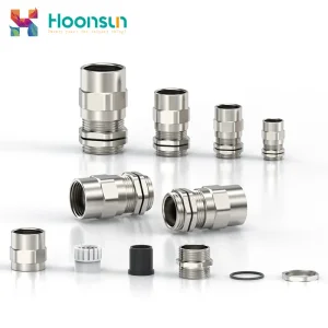
High-Torque, Explosion Proof & Industrial Cable Glands (Tier-2 Series)
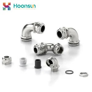
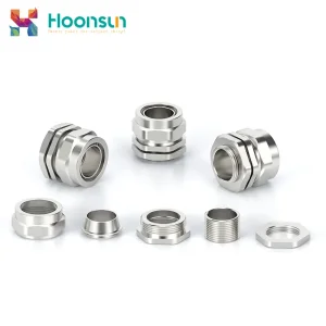
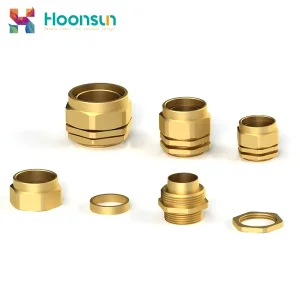
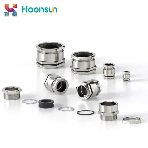
Complete your facility Bill of Materials (BOM) with heavy-duty double lock mechanisms, 90° right angle routings, and specialized armored BW/BWL gland terminations.
Technical Clarification Hub
Electrical Cable Gland Size Chart & Engineering FAQ
Authoritative answers curated by senior Chinese factory application engineers to address complex field installation, sizing calculation, and compliance inquiries.
How do I determine the precise cable gland size from cable outer diameter?
Measure the true outer diameter (OD) of your cable with an accurate digital vernier caliper across the thickest jacket axis. Never use theoretical conductor cross-section (e.g., 3×2.5mm²) alone, as overall jacket thicknesses fluctuate dramatically between PVC, PUR, rubber, and armored braids. Select a gland where your measured cable OD falls within the middle 30% to 70% of the manufacturer's clamping range. This guarantees both long-term elastomeric sealing recovery and mechanical strain relief under thermal cycling.
What is the technical operational difference between IP68 and IP69K?
IP68 (IEC 60529) certifies that equipment can withstand continuous immersion in water under specific manufacturer-declared hydrostatic conditions (typically 3 to 10 bar pressure for 24+ hours). In contrast, IP69K (DIN 40050-9 / ISO 20653) tests against close-range, high-pressure (80 to 100 bar), ultra-high-temperature (+80°C) steam washdowns directed from 0°, 30°, 60°, and 90° angles. For automated food processing, pharmaceutical production, or EV chassis applications, IP69K rated stainless or reinforced polyamide glands are mandatory.
Can I safely adapt a PG thread into a Metric enclosure entry knockout?
Yes, but you must utilize an engineered, nickel-plated brass or nylon thread converter / reducer (e.g., PG to Metric or Metric to PG). You must never force a PG thread directly into an ISO Metric tapped hole, even if the diameters appear close (e.g., PG13.5 major OD is 20.4mm, while M20 is 20.0mm). Their thread pitch (PG13.5 uses 18 TPI / 1.41mm; Metric uses 1.5mm) and flank angles (80° vs 60°) will cause immediate thread galling, irreversible thread stripping, and total ingress containment failure.
When should 316L stainless steel be chosen over nickel-plated brass?
While nickel-plated brass (HPb59-1 / CW614N) offers outstanding mechanical stability and moderate atmospheric protection, 316L (1.4404) austenitic stainless steel is required in environments with high chloride ion concentrations, coastal offshore salt-fog spray, aggressive caustic washdowns (food production CIP processes), and sulfurous chemical refinery fumes. SS316L incorporates 2% to 3% molybdenum, completely mitigating destructive pitting and crevice corrosion under long-term exposure.
Why is tightening torque critical on cable gland installations?
Under-tightening a cable gland prevents the internal elastomeric sleeve (NBR/EPDM/Silicone) from sufficiently flowing into the microscopic surface contours of the cable outer sheath, violating the IP68 barrier and compromising pull-out resistance. Conversely, over-tightening crushes the cable jacket, induces cold-flow conductor pinching, accelerates rubber aging via excessive compression set, and can shear the gland body threads. Always adhere to the recommended torque specifications outlined in our master size chart using a calibrated torque wrench.
What is the function of a vent plug on a sealed electrical enclosure?
When an IP68 electrical enclosure experiences internal heat fluctuations (from transformers, variable frequency drives, or solar irradiation cycles), air inside expands and contracts, creating an intense internal differential pressure or vacuum. This vacuum acts as a mechanical pump, pulling exterior moisture past standard seals. Integrated vent plugs contain an ePTFE hydrophobic and oleophobic membrane that permits continuous bidirectional gaseous airflow (pressure equalization) while stopping liquid water and micro-dust particles dead in their tracks.